
In that case, can't the diode be useful so the motor can be used as a generator also? This circuit is to be used in a motor and I imagine some configurations where the motor is turning using a mechanical force. Placed near the inductor, I'd think it could be flyback diode, but if it was, I would have placed it in parallel with the inductor.Įdit: suppose the inductor receives induced current. I have a schematic of a circuit used to trigger an inductor (for a home-made motor):Įdit: The component A3144 is US5781 (I have its doc along with this schema).Įdit: try Melexis US5781 datasheet here - RMĪpparently, the 1000♟ seems to be here to have a power source near the circuit, but I don't understand the diode 1N4007.
#Tip42 c free
When producing unlimited free energy, having some diodes "backwards" is the least of one's challenges. The action of producing free energy does explain the unusual orientation of the diodes which are correctly oriented if the device acts as an energy source. The device is intended to operate as an alternator to produce the "over unity" energy which is what makes it a perpetual motion machine.
#Tip42 c plus
The device appears to act as a brushless DC motor with 2 hall sensor units as per the circuit below providing position sensing and control plus a number of other magnets and coils to control the rotor and help produce the perpetual motion. In this device the hall sensor is one of a pair which are triggered by magnets which are part of or included in the device rotor.

In a perpetual motion machine anything may be needed.

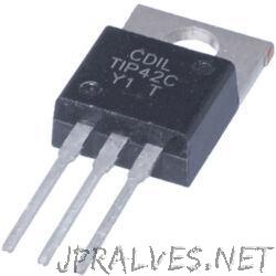
This would in fact switch the coil but this is not the best way to do it in "normal" equipment. The proper way to connect this hall sensor in the diagram below, is to connect ground to ground, IC Vdd to diagram +12V and IC out via a resistor to TIP42C base. It is either incorrect when a US5781 is used, or the diagram is wrong. The diagram below is copied from the perpetual motion machines description document. This is presumably quivalent to Melexis US5781 datasheet here. The switching device shown on the circuit was originally shown in the notes as an A3144, but a footnote says that a US5781 can be used in its place. Pricing and Availability on millions of electronic components from Digi-Key Electronics.Edit: The following question is related to a perpetual motion machine, a "Selfrunning Free Energy Muller MotorGenerator powering a 20 Watt bulb" AOI508 – N-Channel 30 V 22A (Ta), 70A (Tc) 2.5W (Ta), 50W (Tc) Through Hole TO-251A from Alpha & Omega Semiconductor Inc.

Digi-Key Electronics AOI508 | Digi-Key Electronics I'd recommend an N-channel MOSFET instead, such as AOI508. And even then, you will lose up to 1.5V across the transistor, leaving just 10.5V across the fan for poor operation. See "Collector-emitter saturation voltage" on page 4Īrduino can only output 20-30mA, so these transistors won't turn on very hard and not much current will flow unless you put a drive circuit in front of them to boost current flow into the base. To get them to turn on fully and have minimal voltage across them you need a lot of base current. The TIP41C and TIP42C are not very high gain parts. With a 12V supply, the easiest way to do that is to use an NPN to connect the '-' of the motor to Gnd. To do that, control a transistor with a PWM signal. I expect the fans will work better if you control the on/off time of the 12V driving them vs trying to drive them with a lower voltage.


 0 kommentar(er)
